// Hydraulic Power Unit
A long-standing customer has requested the design and manufacture of a new Hydraulic Power Unit to replace and integrate two existing systems into a single, efficient unit.
Design Objectives
Integration and Replacement:
Develop a new Hydraulic Power Unit that consolidates the functions of the two outdated systems into one unified unit.
Component Availability and Maintenance:
Address issues related to the obsolescence of components in the existing systems, which have led to extended downtime and difficulties in obtaining parts. Design the new unit with modern components to ensure availability and ease of maintenance.
Accessibility and Serviceability:
Improve the accessibility of the new unit to facilitate easier servicing and maintenance. The design should focus on reducing downtime by making routine maintenance tasks more manageable.
Operational Impact:
Minimize any potential downtime, as the machine’s performance is critical to the entire supply chain. The new unit should be designed to enhance reliability and reduce the risk of operational interruptions.
Product Quality:
Ensure that the new unit addresses and eliminates the intermittent faults that have been affecting product quality in the existing systems.
Design
Evaluation and Integration Feasibility:
We conducted a detailed analysis to determine the feasibility of combining the two originally separate hydraulic systems into a single Hydraulic Power Unit. Calculations confirmed that one unit could effectively manage the functions of both systems.
The unit was designed to specific dimensions to ensure it could be seamlessly integrated into the machine’s existing framework. This approach was intended to facilitate better access for servicing and maintenance.
Control System Integration:
We worked closely with software engineers to adapt the control system to work effectively with the new hydraulic power unit, ensuring compatibility and seamless operation.
Installation Considerations:
We addressed the challenge of installing the unit without access to an overhead crane. Developed a detailed plan for installation that accounted for this constraint, ensuring that the unit could be positioned and secured effectively within the machine’s framework.
This design procedure outlines the steps taken to integrate and optimize the hydraulic power unit, focusing on efficient operation, ease of maintenance, and practical installation within existing constraints.
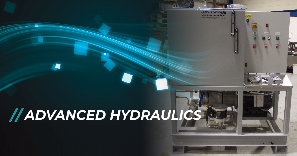
Manufacture
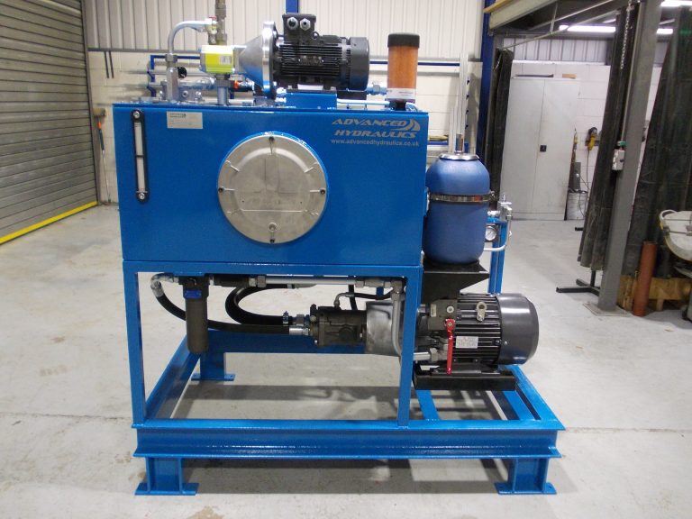
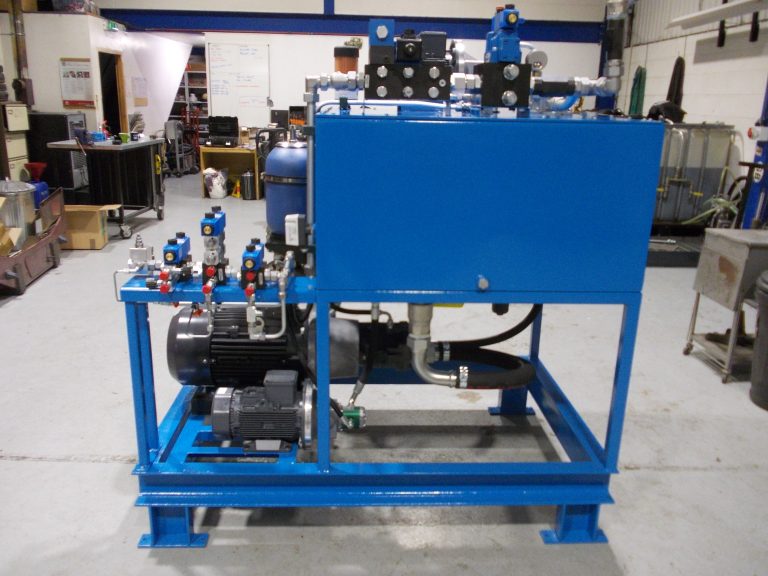
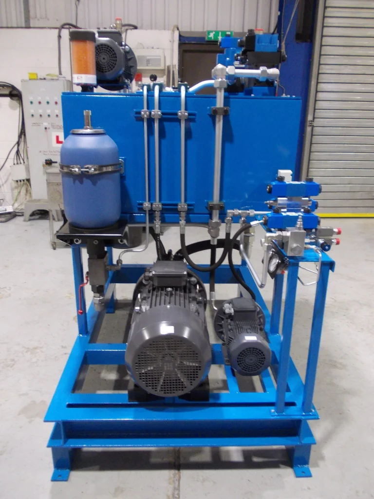
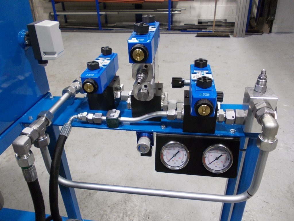
The manufacturing process for the hydraulic power unit began with the construction of a 500-litre reservoir, which was mounted on a robust skid frame. The frame was designed to provide stability and facilitate handling during installation. A custom valve stand was fabricated to specific dimensions to streamline installation and ensure seamless integration with the existing system. To simplify servicing and maintenance, a large inspection hatch was incorporated into the reservoir design, allowing for easy access during routine checks and repairs.
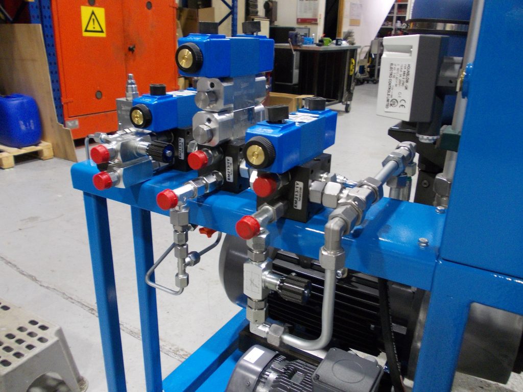
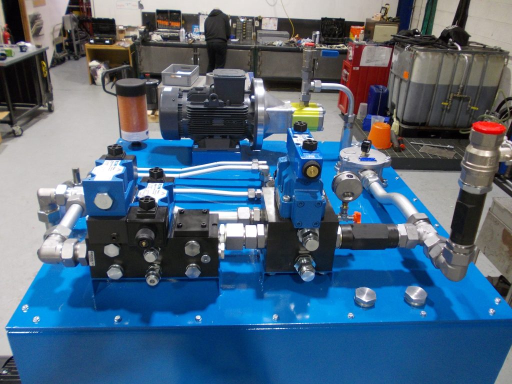
For the hydraulic system, the block splitting function was addressed by installing high efficiency electric motor, which was mounted horizontally on the framework using anti-vibration rods. This motor was coupled to a variable displacement, pressure-compensated piston pump to deliver precise hydraulic power. An inline pressure filter was integrated with a visual clogging indicator and a bypass to filter down to 10µm absolute, ensuring the hydraulic fluid remained clean and protecting system components. A 10-litre accumulator, equipped with an accumulator safety block, was added to manage pressure fluctuations and maintain system stability.
The block rotate function was managed by mounting an electric motor coupled via a bellhousing and coupling to a gear pump. Another inline pressure filter, like the one used for the splitting function, was included to filter down to 10µm absolute, ensuring clean fluid for the rotating function.
To manage return flow, oil from both systems was directed through a tank lid-mounted return filter. This filter featured a visual clogging indicator and a bypass for filtering down to 16µm nominal, maintaining the cleanliness of the return flow and preventing contamination of the system.
The entire manufacturing process was designed to ensure efficient operation, easy maintenance, and reliable performance of the hydraulic power unit.