// High pressure hydraulic test rig
Key Requirements
Brief:
Advanced Hydraulics has been commissioned by a well-established cylinder manufacturer to design and manufacture a high-pressure hydraulic power unit for testing hydraulic accumulators.
The unit must be engineered to handle a maximum test pressure of 36,500 PSI (approximately 2500 bar). This requirement necessitates the selection of high-quality materials and components capable of withstanding such extreme pressures reliably and safely.
Design considerations for the unit emphasize ease of maintenance and service. This involves creating a design that features accessible components, straightforward replacement procedures, and minimal downtime during servicing. Clear labelling, a modular design, and easily reachable maintenance points will be integral to achieving this goal.
Operator feedback and ergonomics are also critical in the design process. The unit should offer clear visual feedback to the operator for accurate monitoring and control. Ergonomic features, such as a user-friendly control panel, easy-to-read gauges, and intuitive interfaces, will enhance usability and ensure efficient operation.
Furthermore, ease of installation is a key consideration. The system should be designed with manageable dimensions and weight, and provide clear installation instructions. Connections and fittings must be straightforward to handle, facilitating a smooth installation process.
The objective is to develop a high-pressure hydraulic power unit that meets stringent performance requirements for accumulator testing, while also being user-friendly, maintainable, and easy to install. The design should combine robust engineering with practical features to support efficient and reliable operation in a demanding testing environment.
Design:
Our design process for the high-pressure hydraulic power unit began with detailed calculations for each component of the system. Using SolidWorks, we developed an initial design which was then presented to the customer for approval.
We considered several critical factors during the design phase. We started by assessing the physical space available on-site, including the positioning of the operator and the orientation of the outlet connections. These considerations ensured that the system would fit seamlessly into the existing environment and be ergonomically suitable for the operator.
Ease of maintenance and servicing was another key factor. We designed the system with accessibility in mind, ensuring that routine maintenance tasks could be performed efficiently.
Our calculations indicated the need for an offline cooler and filter to enhance the longevity of the power unit and its components. This addition helps to maintain optimal operating conditions and prolongs the service life of the system.
To achieve the required pressure of 36,500 PSI, we specified an air/oil intensifier. For the high-pressure section of the system, we used stainless steel fittings and tubing, chosen for their ability to withstand the extreme pressures involved.
In summary, our design process integrated precise calculations, ergonomic considerations, and component selection to create a high-pressure hydraulic power unit that meets both performance and practical requirements.
Manufacture:
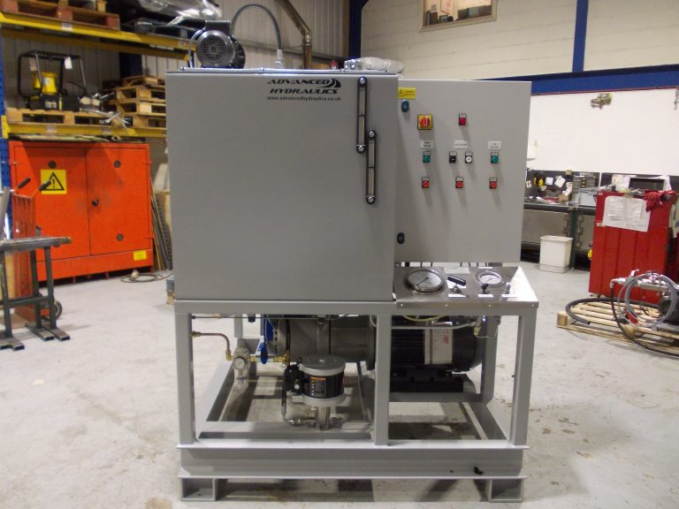
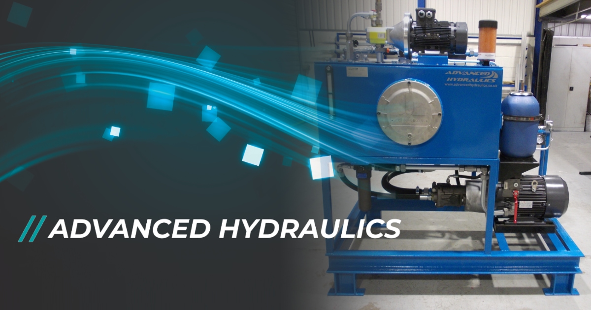
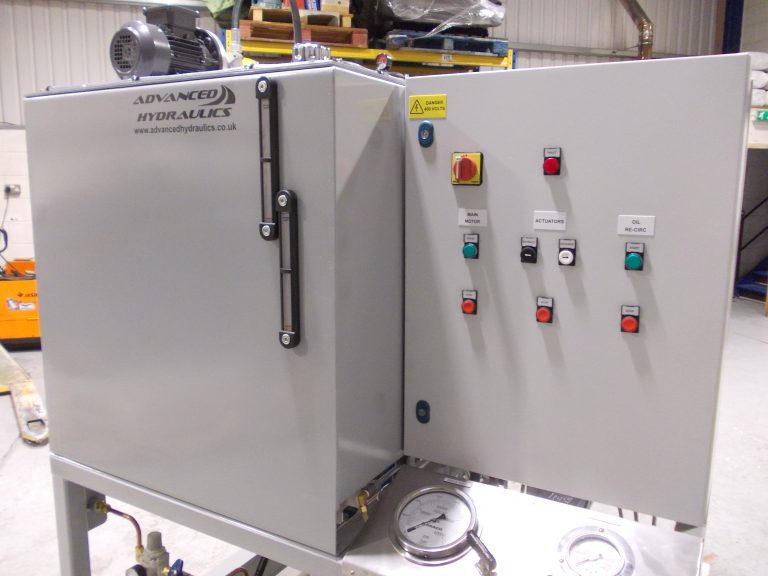
The hydraulic power unit was completed within the quoted 12-week timeframe. The unit features a 1000-litre reservoir constructed from mild steel, equipped with a filler/breather, a visual level gauge, and a split lid for easy access.
The system includes a high efficiency electric motor coupled to a radial piston pump, designed to produce a maximum pressure of 300 bar.
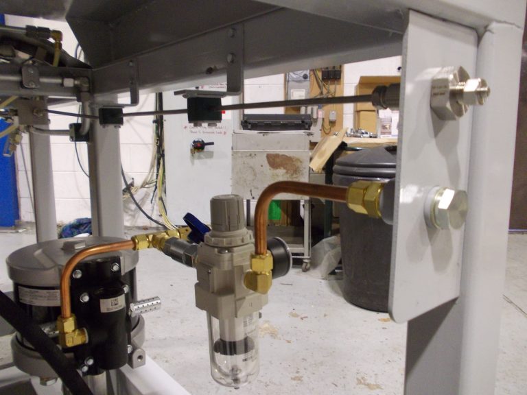
The high-pressure air/oil intensifier unit, capable of producing a maximum pressure of 36,500 PSI, is incorporated directly onto the frame of the hydraulic power unit.
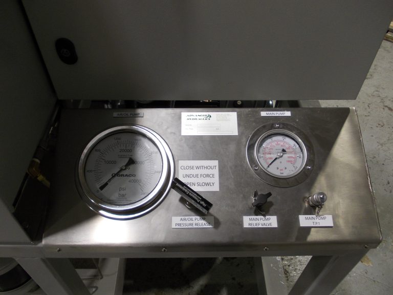
The pipework incorporates both a pressure transducer and a temperature transducer with a 4-20 mA output, along with a plug-in point for a particle analyser. A 4-inch pressure gauge is mounted on the panel, which is affixed to a subframe.
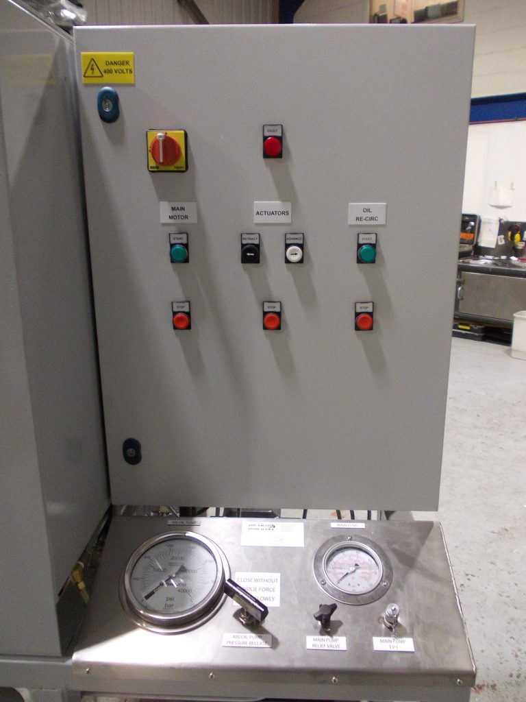
The unit also includes an electrical panel with stop/start and isolate push buttons, as well as extend/retract push buttons for operational control.
