// Energy recovery system
brief:
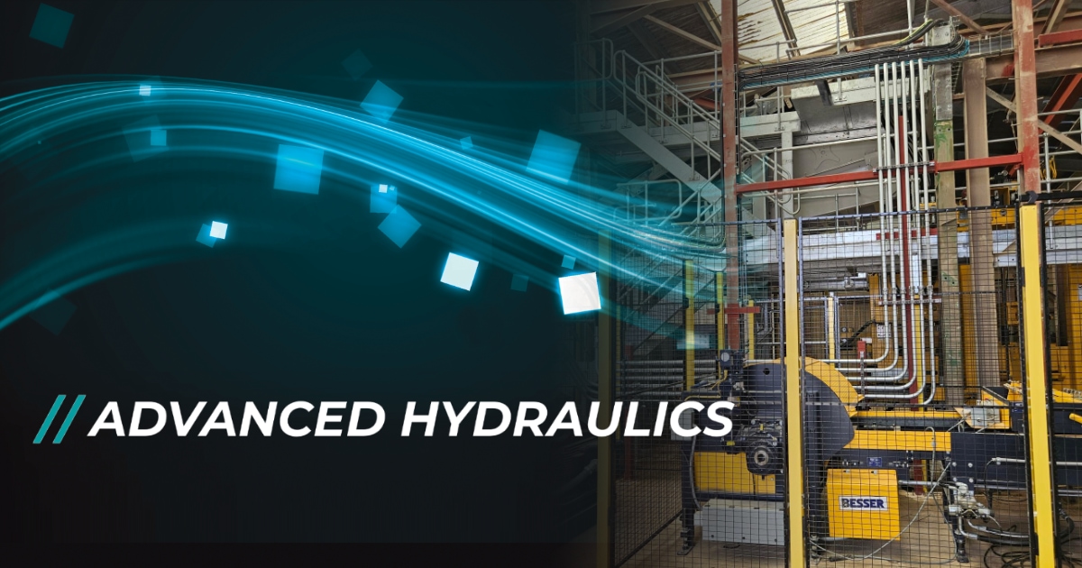
Advanced Hydraulics was approached by a new customer seeking a custom-designed hydraulic system for their innovative road-based energy harvesting system.
The customer had been let down at the last minute by another supplier, leaving them with a tight deadline. As a result, the system needed to be designed and built within just four weeks.
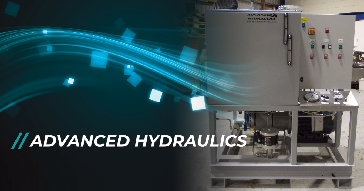
The unit needed to fit inside a prefabricated cabin, requiring precise design specifications. Additionally, to help meet the tight deadline, we were asked to incorporate brackets for electrical components into our design, streamlining the installation process.
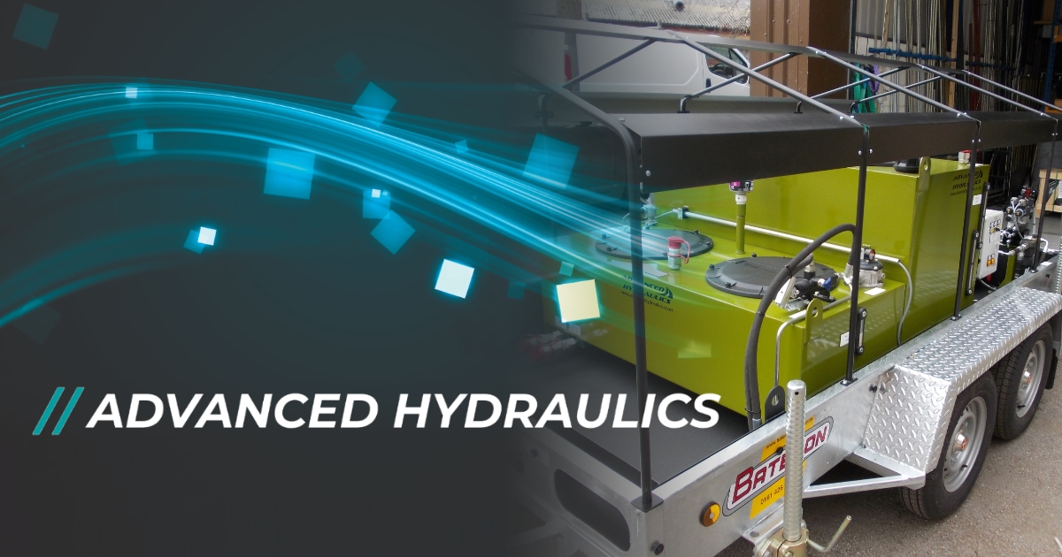
Additionally, the skid package should be equipped with lifting eyes to facilitate the safe and efficient lifting of the entire unit.


Design:
The customer provided us with a schematic drawing and a general arrangement drawing as a starting point for the design. However, due to the unavailability of many components caused by long delivery times, we had to make compromises and modify the design to ensure the project could be completed within the required timeframe.
With a strong emphasis on efficiency, the routing of pipework and the selection of fittings were critical aspects of the design. Ensuring optimal flow and minimal pressure loss was essential to meet the performance requirements.

Manufacture:
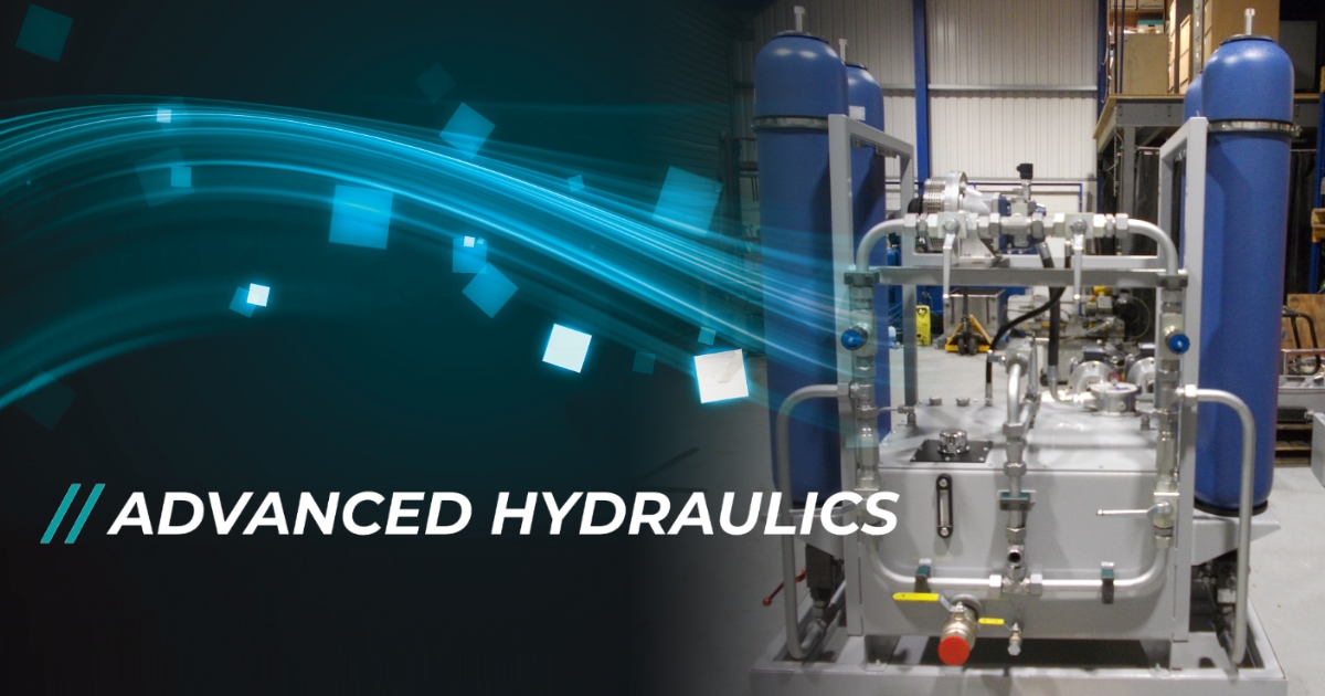
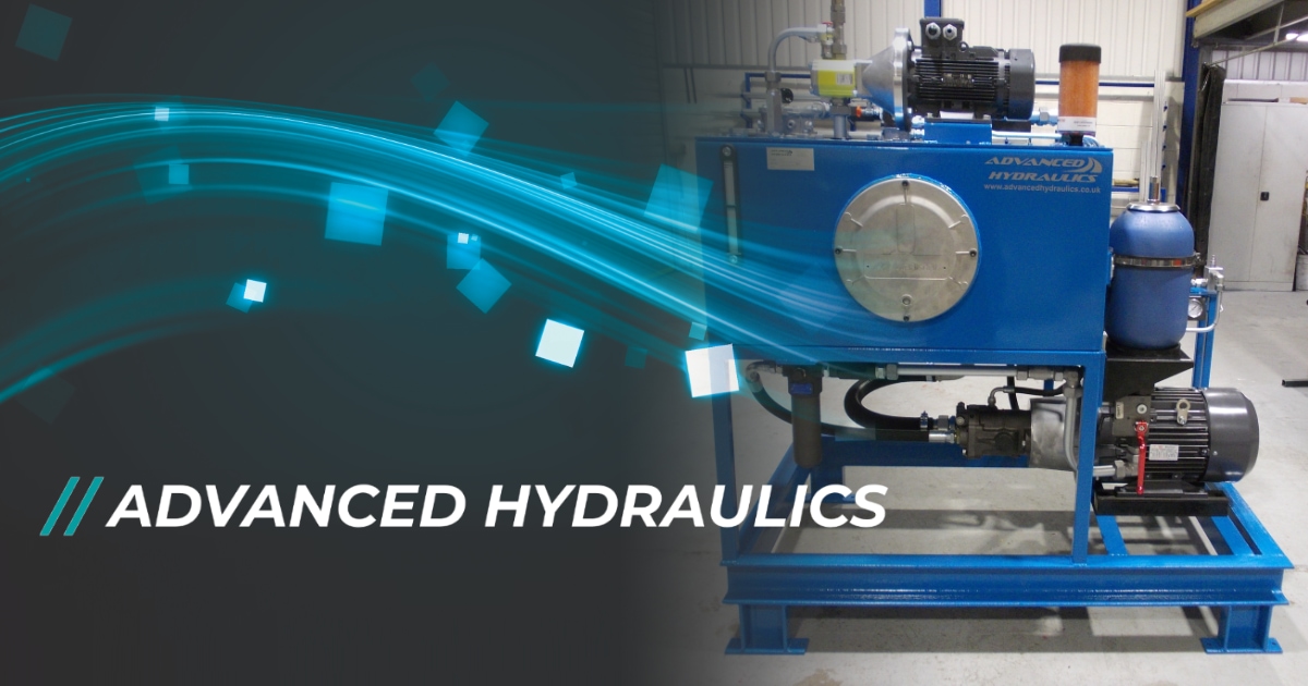
Manufacturing began with the fabrication of the skid frame, which was designed to securely integrate the 300-litre tank and a full-capacity bund. This initial step ensured a sturdy foundation for the entire hydraulic power unit, providing both structural support and containment for any potential leaks.
The system required four industrial bladder accumulators, each with a capacity of 35 litres. These accumulators were carefully mounted onto the frame. The high-pressure circuit included two accumulators connected inline with safety blocks and relief valves to protect against overpressure. High-pressure ball valves were installed for isolation, along with pressure transmitters and flow control valves to regulate and monitor system performance. The low-pressure circuit followed a similar setup, with two accumulators, safety blocks, relief valves, and isolation ball valves to ensure reliability and safety.
The control circuit was mounted vertically on the unit, designed for easy access to various valves and take-off points. This vertical orientation facilitated maintenance and adjustment, ensuring that all critical components were within reach. A manually operated relief/unloading valve was installed in the pressure line, along with a test port for diagnostic purposes.
The hydraulic motor, rated at 35 cc/rev, was connected to the system with pressure-compensated flow control valves and pressure transmitters to ensure precise control and monitoring of the hydraulic pressure. The motor’s connection was integrated with the inlet and return ports mounted at the back of the tank, allowing seamless connection to the external hydraulic system.
Once all components were installed, the entire unit underwent rigorous testing to ensure that all connections, valves, and circuits operated according to specifications. The unit was checked for leaks, pressure stability, and overall performance before being cleared for delivery to the customer. The final assembly, mounted on the skid package, was verified for ease of lifting and transport, ensuring that the HPU unit met all the design and functional requirements set forth in the project.